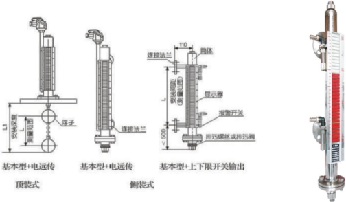
According to the principle of buoyancy, the rise and fall of float along with the liquid level in the measuring tube and move up, down, float in the permanent magnet steel through coupling, drive the red and white double column turn 180 °, column from white to red level rises, falls from red to white, so as to realize liquid level instructions.
2, electric remote
Installed on the float liquid level gauge transducer, move up and down through the float, the magnetic coupling effect makes the measuring element inside the guide rod action, in turn get resistance signal change, into 0 ~ 10 ma, or 4 ~ 20 ma standard signal output, and display instrument or computer connection, achieve far eastone.
3, on the lower limit switch output
On the level set by the user on the riser, the lower limit position controller, the controller inside the self-hold effect of reed switch, the use of magnetic float level with the mobile so that reed switch action, realize the alarm or limit control.

1, on the lower limit switch output
By with the keep the role of reed switch and converter, reed switch converter installed on site), and the control room, three on the contact switch is provided by the converter.
2, electric remote
Consists of two parts, measuring unit and transmitting unit.
3, safety explosion-proof
A belt in the explosion-proof, and lower limit switch output type
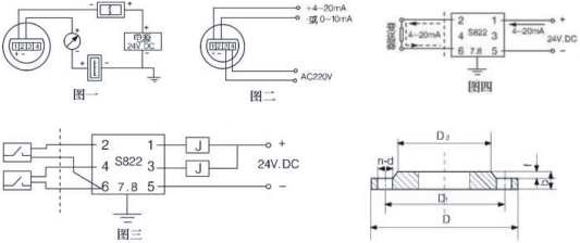
Explosion-proof switch by the reed switch and relay contact with security gate, can be directly to the user to provide a normally open or normally closed contacts.If users need more contact can design special order.(figure 3)
B with the explosion-proof type far eastone
Suitable for use in ∏ type electrical equipment (factory), class C gas, maximum surface temperature category T4 (135 ℃).(figure 4)
C using the note
(1) transmitter shell is equipped with an external, users must be reliable grounding.
(2) the use of safety barrier shall comply with the relevant instructions.
(3) transmitter and safety barrier Ann the connecting cable in two core shielded cable, wire cross-sectional area > 0.5 m, cable allows distributed capacitance of 0.8 u F.

Users should bring along their own flange
| Type of installation | The main body material | Nominal diameter | Nominal pressure | D | D1 | D2 | n | d | f | b |
| Lateral loading | Stainless steel | 20 | 4.0 | 105 | 75 | 56 | 4 | 14 | 2 | 16 |
| ABS | 20 | 10 | 105 | 75 | 56 | 4 | 14 | 2 | 16 | |
| Top loading | Stainless steel | 200 | 2.5 | 360 | 310 | 274 | 12 | 26 | 3 | 32 |
| ABS | 200 | 0.6 | 320 | 280 | 274 | 8 | 8 | 3 | 32 |
The main technical indicators
| Install form content | Side mounted | Top mounted | |
| Install the spacing (measuring range) | Stainless steel | 500~5000(mm) | 500-2500(mm) |
| ABS、PP-R | 500~4000(mm) | ||
| Pressure of work | 0.6,1.6,2.5,4.0MPa | 0.6,1.6,2.5MPa | |
| Medium density | >0。6g/c | >0.76g/c | |
| Flange connection | Stainless steel | Flange 20-40 (3/4 "PN1.0-4.0) (GB9119-88) | Flange 200-25 (DN200 PN1.6) (GB9119-88) |
| ABS | Flange 20-10 (3/4 "PN1.0) (GB9119-88) | Flange 200-6 (DN200 PN0.6) (GB9119-88) | |
| The main body material | ICr18Ni9Ti, ABS, PP - R (work pressure 0.6 MPa) | ||
| Medium temperature | -40~100℃(ABS、PP-R:-40~80℃) | ||
| The environment temperature | - 40 ~ + 70 ℃ | ||
| Error value | ±100mm | ||
| Medium viscosity | ≤1st(10-4 | ||
| , on the floor Switch output | 1, control sensitivity: 10 mm 2, the output contacts capacity: AC220V 2 a 3, contact life: 5 x 104 times 4, explosion-proof features: iaIICT4 intrinsically safe | ||
| Far eastone, Continuous display | 1, precision: plus or minus 1.5% 2, the output load: 750 Ω 3, the output signal: 0 ~ 10 ma output, 220 v AC power supply 4 ~ 20 ma output, 24 v DC two-wire system 4, explosion-proof features: iaIICT4 intrinsically safe | ||
| UHZ inspcetion double column type level gauge | ||||||||
| 1 side mounted 2 the top mounted | installation | |||||||
| 1 1Cr18Ni9Ti 2 ABS 3 PP-R | The main body material | |||||||
| 1 0.6MPa 2 1.6MPa 3 2.5MPa 4 4.0Mpa | Nominal pressure | |||||||
| 1 basic 2 take lower limit switch output 3 charged far eastone (0 ~ 10 ma, 220 v, AC) 4 charged far eastone (4 ~ 20 ma output, 24 v, DC) 5 zone in the explosion-proof type (4 ~ 20 ma, 24 v, DC) 6 zone in the explosion-proof type on the lower limit switch output | type | |||||||
| L installation spacing (measuring range) | ||||||||
| L1 installation depth (top mounted (0 ~ 4000 mm optional) | ||||||||
| Medium density rho (g/c | ||||||||
| 2 | 2 | 1 | 1 | =2500mm | L1=3000mm | Rho = 0.8 g/c | For example, | |
 Mail
Mail Chinese
 English


