 Mail
Mail Chinese
 English


An overview,
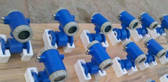
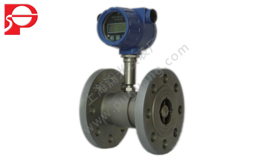
LWGY turbine flowmeter is composed of turbine flow sensor and display instrument, is the factory using foreign advanced technology manufacturing, one of the most ideal flowmeter is liquid measurement.Flow meter has simple structure, high precision, convenient in installation and maintenance, etc.The products are widely used in petroleum, chemical industry, metallurgy, water supply, paper making, environmental protection, food and other fields, and is suitable for the measurement in a closed pipe with 1 cr18ni9ti stainless steel, 2 cr13 and corrode corundum Al2O3, cemented carbide, and no fiber, particle impurities such as liquid.If with display instrument with special functions, can automatically quantitative control, such as excessive alarm purposes.
Second, the product features:
1. The sensor is cemented carbide bearing thrust type, not only guarantee the accuracy, and improve the wear resistance.
2. Simple structure, strong and tear open outfit is convenient.
3. Wide measuring range, low threshold velocity.
4. Small pressure loss, good repeatability, high precision.
5. Have high resistance to electromagnetic interference and vibration resistance.
Third, how it works:
Fluid flowing through the sensor shell, as a result of the impeller blade and flow to a certain point of view, the impact of fluid blade with rotational torque, to overcome the friction torque and fluid resistance, blade rotation speed stability after the moment balance, under certain conditions, the speed is proportional to the velocity of flow, because there are magnetic conductivity blade, it is in the signal detector (consists of permanent magnets and coils) magnetic field, rotating blade cutting lines, periodically changing coil magnetic flux, so that the coil ends induction electric
The pulse signal, the signal after amplifier amplification plastic, form a certain amplitude of continuous rectangular pulse wave, can be spread far to display instrument, show the instantaneous flow and cumulative amount of fluid.Within the scope of a certain flow, pulse frequency f and flows through the sensor of fluid is proportional to the instantaneous flow rate Q, flow equation is:

Type:
F - pulse frequency (Hz);
K - the instrument coefficient of sensor 1 / m3, given by the check list.If [1 / L] as the unit
Q - fluid transient flow (working conditions) (m3 / h),
3600 - conversion factor.
Coefficient of each sensor of the instrument in the calibration certificate will be completed by the manufacturer, set into the display instrument of form a complete set of k value, can show the instantaneous flow and cumulative total.
4. The main technical performance:
1. Nominal diameter (4 ~ 200) mm basic parameters are shown in table 1;
2. : (20 ~ 80 ℃), medium temperature (20 ~ 120 ℃;
3. The environment temperature (20 ℃ ~ 55);
4. The accuracy of the quasi: plus or minus 0.2%, plus or minus 0.5%, plus or minus 1%;
5. The detector signal transmission system: three-wire system voltage pulse (three core shielded cable);
6. Power supply voltage: 12 V + / - 0.144 V, current: 10 or less ma;
7. The output voltage amplitude, high level 8 or higher V, low level 0.8 V or less;
8. Transmission distance, the distance of the sensor to display instrument of up to 250 meters;
9. The scene display type power supply: 3 v (lithium batteries, can use continuously 3 years);
10. Display mode: the liquid crystal display instantaneous flow and cumulative flow;
11. The scene shows with signal output power supply: 24 v.Two wire system 4 ~ 20 ma output current, remote transmission distance of 500 meters.
Table 1
LWGY□ | Twenty - | - | - | - | Said Ming | ||||
class type | LWGYA | Flow sensor pulse output three wire system, + 12 v power supply; | |||||||
LWGYB | The display type 3 v battery power supply; | ||||||||
LWGYC | Live show with 4 ~ 20 ma or pulse output, + 24 v power supply; | ||||||||
LWGYD | The flow transmitter 4 ~ 20 ma output, + 24 v power supply. | ||||||||
The male According to tong diameter | 4 | Normal flow range m3/h | 0.04 ~ 0.25 | Expand the flow range m3/h | 0.04 ~ 0.4 | ||||
6 | 0.1 ~ 0.6 | 0.06 ~ 0.6 | |||||||
10 | 0.2 ~ 1.2 | 0.15 ~ 1.5 | |||||||
15 | 0.6 ~ 6 | 0.4 ~ 8 | |||||||
20 | 0.8 ~ 8 | 0.45 ~ 9 | |||||||
25 | 1 ~ 10 | 0.5 ~ 10 | |||||||
32 | 1.5 ~ 15 | 0.75 ~ 15 | |||||||
40 | 2 ~ 20 | 1 ~ 20 | |||||||
50 | 4 ~ 40 | 2 ~ 40 | |||||||
65 | 7 ~ 70 | 3.5 ~ 70 | |||||||
80 | 10 to 100 | 5 ~ 100 | |||||||
100 | 20 ~ 200 | 10 to 200 | |||||||
125 | 25 ~ 250 | 12.5 ~ 250 | |||||||
150 | 30 ~ 300 | 15-300 | |||||||
200 | 80 ~ 800 | 40 ~ 800 | |||||||
prevent detonation | No mark for the explosion proof type | ||||||||
B | Explosion-proof type | ||||||||
precision level | A | 0.2 accuracy | |||||||
B | 0.5 accuracy | ||||||||
C | 1.0 accuracy | ||||||||
The turbine type | A | Normal flow range | |||||||
B | Expand the flow range | ||||||||
Description: DN4 ~ DN40 pipe diameter of the sensor for the threaded connection, with a straight pipe and filter, before and after the maximum pressure is 6.3 Mpa. (~ DN200 pipe diameter of the sensor for flange connection, the maximum pressure of 2.5 Mpa. DN15 ~ DN40 straight pipe before and after the pipe diameter is optional or union, material of carbon steel and stainless steel. DN15 ~ DN40 diameter for flange connection, ordering. Taken the high pressure type and special request ordering. | |||||||||
Five, the exterior size:
Sensor installation method according to different specifications, using thread or flange connection, the installation method as shown in figure a, figure 2, figure 3, figure 4, figure 5.Installation dimensions are shown in table 2.
Graph one, DN4 - DN10 sensor structure schematic and installation size

Filter 2. Straight pipe before 3. 4. The impeller preamplifier 5. Case 6. After the straight pipe
Figure 2, the filter structure
Clamping ring on 1. 2. The bolt 4 x 14 (3) 4 gasket sealing washer 5. Wire 1 cr18ni9ti - 0.8 x 2.5 6. Screen pack 7.
FIG. 3, DN15 ~ DN40 sensor structure schematic and installation size

1. Case 2. Guide before a 3. 4. The impeller leads to a 5. After preamplifier
FIG. 4, LWGY - 50 ~ 200 sensor structure diagram and installation size

1. 2 ball bearing guide before a 3. Flange 4. Case 5. Preamplifier 6. Impeller 7. 8. Bearing axis

Table 2 unit (mm)
model | Nominal diameter | L | H | G | Lˊ | D | d | Number of holes |
LWGY-4 | 4 | 295 | 145 | G1/2 | 195 | |||
LWGY-6 | 6 | 330 | 145 | G1/2 | 230 | |||
LWGY-10 | 10 | 450 | 165 | G1/2 | 350 | |||
LWGY-15 | 15 | 75 | 173 | G1 | ||||
LWGY-20 | 20 | 85 | 178 | G1 | ||||
LWGY-25 | 25 | 100 | 180 | G1 1/4 | ||||
LWGY-32 | 32 | 120 | 190 | G1 1/2 | ||||
LWGY-40 | 40 | 140 | 178 | G2 | ||||
LWGY-50 | 50 | 150 | 252 | ø 125 | ø 18 | 4 | ||
LWGY-65 | 65 | 175 | 265 | ø 146 | ø 18 | 8 | ||
LWGY-80 | 80 | 200 | 287 | ø 160 | ø 18 | 8 | ||
LWGY-100 | 100 | 220 | 322 | ø 180 | ø 18 | 8 | ||
LWGY-125 | 125 | 240 | 335 | ø 220 | ø 26 | 8 | ||
LWGY-150 | 150 | 300 | 367 | ø 250 | ø 25 | 8 | ||
LWGY-200 | 200 | 360 | 415 | ø 295 | ø 23 | 12 |
Note: the flange standards: GB/T9112, 9113, 9115, 9116, 9117-2000 national standards;
DN - 10 ~ DN - 150 2.5 MPa pressure;DN - 200 1.0 MPa pressure;
Six, installation requirements:
Flow meter can be installed in horizontal or vertical, the vertical installation direction of fluid flow from the bottom up, the liquid must be full of pipes, can not have bubbles;Sensor shell with the liquid flow direction to the direction of arrow indicates flow;Straight pipe before and after the sensor requirements (see figure 6), the upstream end should have at least 10
Times the length of the nominal diameter of straight pipe, the downstream end shall be not less than five times the nominal diameter of straight pipe section, its inner surface should be smooth and clean, no dent, fouling and defects such as peeling.The pipe axis of sensor shall be the adjacent pipe axis alignment, connecting sealing gasket may not deep into the pipe cavity;Sensors should be far away from the external electric field, magnetic field, the effective shielding measures should be taken when necessary, to avoid the outside interference.
In order to does not affect the normal liquid delivery, maintenance Suggestions in the installation of sensors, install bypass pipe.
Sensor open when installation, please get amplifier and plug the waterproof processing.Sensors and display instrument connection as shown in figure 5.
When the fluid contains impurities, should be equipped with filter, filter mesh according to the flow of impurities, as a general rule, be 20 ~ 60 mesh.When mixed with the free gas in the fluid, should add the venting device.The whole pipeline system should be well sealed.Users should fully understand the corrosion situation of measured medium, fight sensor from corrosion.
Seven, the use of
Measured liquid mixer when using, should maintain clean, do not contain impurities such as fiber and particles.
Sensor when start to use, should be to slowly filled with liquid sensor, and then open the outlet valve (the valve should be installed in the back-end flow meters), it is strictly prohibited to sensors in liquid state under high velocity impact.
The maintenance period of mixer sensors usually for half a year.Maintenance when cleaning, please note that you are the measuring chamber of damaged parts, especially in the impeller.Please watch the orientation and the position of the impeller when assembling.
Sensor need not when, should be clean inside liquid, dry and after on both ends of the sensor and protective cover, prevent dirt to enter, and then placed in a dry place preservation.(this is very important)
Pieces with the filter should be cleaned regularly, need not when should clean the internal liquid, like sensors, dustproof set, placed in a dry place preservation.
Pieces of the sensor can overhead transmission cables or buried (buried iron pipe should be set.
In front of the sensor installation, first with the display instrument or oscilloscope connected wires, power supply, with my mouth to blow or hand dial the impeller, make its rapid rotation observation have showed that sensor installation again when have shown.If no display, should check the relevant parts, troubleshooting.

