 Mail
Mail Chinese
 English


One, the introduction:
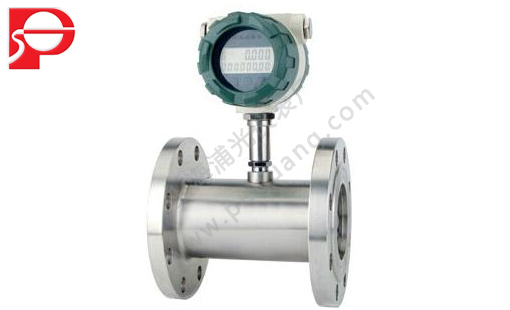
LWG series turbine flow meter adopts advanced ultra low power single chip microcomputer technology of turbine flow sensor and display the integration of integrating new intelligent instrument, through the micro processing unit consists of temperature and pressure testing of analog channel, the flow sensor channel acquisition signal is carried out in accordance with the gas equation of temperature and pressure compensation, automatic compression factor correction, on the LCD screen will all data (instantaneous flow and cumulative flow rate and the total cumulative flow, temperature, pressure, time, date and battery) intuitive display, and to output condition, standard of pulse signal, 4-20 ma, RS485, IC signal such as a variety of communication signals.
Second, the measuring principle:
LWG series turbine flow meter is a fluid flowing through the principle of the sensor shell, because of the impeller blade and flow to a certain Angle, the fluid force makes the blade with rotational torque, to overcome the friction torque and fluid resistance, blade rotation speed stability after the moment balance, under certain conditions, the speed is proportional to the velocity of flow, because there are magnetic conductivity blade, it is in the signal detector (consists of permanent magnets and coils) magnetic field, rotating blade cutting lines, periodically changing coil magnetic flux, so that the coil ends of inductive electric pulse signal, the signal after amplifier amplification plastic, form a certain amplitude of continuous rectangular pulse wave, can be spread far to display instrument, show the instantaneous flow and cumulative amount of the fluid.Within the scope of a certain flow, pulse frequency f and flows through the sensor of fluid is proportional to the instantaneous flow rate Q, flow equation is: Q = 3600 x f/k;Type:
F - pulse frequency (Hz);
K - the instrument coefficient of sensor 1 / m3, given by the check list.If [1 / L] as the unit
Q - fluid transient flow (working conditions) (m3 / h),
3600 - conversion factor.
Coefficient of each sensor of the instrument in the calibration certificate will be completed by the manufacturer, set into the display instrument of form a complete set of k value, can show the instantaneous flow and cumulative total.
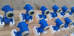
Product use:
LWG turbine flow sensor and display instrument of turbine flow meter.Sensor has high precision, good repeatability, long life characteristics such as simple operation.Can be widely used in petroleum, chemical industry, metallurgy, paper making industries such as measuring the volume of fluid transient flow and the total volume.
Four, the main characteristics of turbine flowmeter:
1, small pressure loss, impeller has antiseptic function;
2, USES the advanced ultra low power single chip microcomputer technology, the machine has strong function, low power consumption, superior performance;
3, which has the function of nonlinear compensation accuracy intelligent traffic monitor.Accuracy of correction formula is better than that of + / - 0.02%;
4, meter coefficient can be set up by the key online and can be displayed on the LCD screen, LCD screen clear intuitive, reliability;
Block 5, the EEPROM to cumulative flow, instrument coefficient of power-fail protection, protection of more than 10 years;
6, using central processing unit (CPU), high performance MCU to complete data collection, processing and display output of cumulative flow transient flow with;
7, convenient screen man-machine interface, data transmission in the form of standard 485;
8, the whole hard alloy (tungsten carbide) shielding cantilever beam structure bearing, integrating rotating bearing with pressure bearing, bearing life can be greatly improved, and can work in a small amount of sediment and dirt in the medium of;
9, with 1 cr18ni9ti stainless steel construction and all (turbine adopts 2 cr13) anti-corrosion performance is good;
10, easy maintenance, since the structure of the rectifier, smaller and lighter, simple structure, can be combined in a short period of time to open it, internal cleaning single;
11, have a stronger ability to resist magnetic disturbance and vibration, reliable performance, long service life limit velocity is low, wide measuring range.
12, the LCD shows clear intuitive display type, low power consumption, 3 v lithium batteries can run more than 5 years in a row, corrosion resistance, suitable for acid and alkali solution.
Five, the technical parameters of the turbine flowmeter:
Nominal diameter: pipeline: DN4 DN200 ~;
Insert: DN100 ~ DN2000;
Precision level: pipeline: + / - 0.5 level;
Plug-in: + / - 1.0 level;
Ambient temperature: 20 ℃ to 50 ℃;
Medium temperature: liquid measurement: - 20 ℃ ~ 120 ℃;
Measuring gas: - 20 ℃ ~ 80 ℃;
The atmospheric pressure: 86 kpa to 106 kpa.
Nominal pressure: 1.6 Mpa, 2.5 Mpa, 6.4 Mpa, 25 Mpa.
Explosion-proof level: ExdIIBT4;
Connection mode: threaded connection, flange clamp, flange connection, plug, etc.;
Straight pipe section requirements: gas: upstream should be 10 or more dn, downstream straight pipe should be 5 or more dn.
Liquid: straight pipe upstream should be 20 or more dn, downstream straight pipe should be 5 or more dn.
Plug-in: straight pipe upstream should be 20 or more DS, downstream straight pipe should be 7 or higher DS (DS for pipeline measured diameter);
Display mode: far eastone show: pulse output, the output current (match display instrument);
Live show: eight LCD display cumulative flow, unit (m3);
Four transient flow, LCD display unit (m3 / h), battery, frequency and velocity
Temperature and pressure compensation type:
According to the standard criteria for instantaneous flow and cumulative flow;
Show the current pressure, temperature, battery voltage;
Pulse output, output functions: p - p values determined by power supply;
4 ~ 20 ma two wire output current;
Unit volume pulse output and the original pulse sensor output;
With RS485 communication interface;
Power supply: DC5 ~ 24 v.
Standard 3 v lithium battery installed on the instrument internal can use eight consecutive years;
Temperature pressure compensation type 3 v lithium battery installed within the instrument can be continuous use of more than 4 years;
Transmission distance, distance sensor to display up to 500 m.
Six, turbine flowmeter display function:
1, according to standard criteria for instantaneous flow and cumulative flow;
2, according to working condition of the working condition of the instantaneous flow and cumulative flow;
3, according to the current pressure, temperature, battery voltage;
4, shows the date and the clock.
Seven, model and standard configuration:
LWGY type: basic sensor.Note: without the scene, according to the output pulse signal.Standard for the flameproof products.
LWGY - type A: 4-20 ma transmitter.Note: without the scene, according to the standard 4-20 ma output current signal.The standard for explosion-proof products (ExdIIBT6, explosion-proof number: CE061580).
LWGY - B: intelligent display on site.Note: double row liquid crystal header, the scene at the same time show the instantaneous flow and cumulative flow, lithium batteries, battery can use more than three years in a row, no signal output.The standard for explosion-proof products (ExdIIBT6, explosion-proof number: CE061580).
LWGY - C: intelligent integration type.Note: double row liquid crystal header, the scene at the same time show the instantaneous flow and cumulative flow, outside for 24 VDC, output standard 4-20 mA current signal, the standard for explosion-proof products (ExdIIBT6, explosion-proof number: CE061580).
Eight, the turbine flowmeter using requirements:
Measured liquid 1, when using, should maintain clean, do not contain impurities such as fiber and particles.
2, sensors, at the beginning of the use should be to slowly filled with liquid sensor, and then open the outlet valve (the valve should be installed in the back-end flow meters), it is strictly prohibited to sensors in liquid state under high velocity impact.
The maintenance period of 3, sensors, generally for half a year.Maintenance when cleaning, please note that you are the measuring chamber of damaged parts, especially in the impeller.Please watch the orientation and the position of the impeller when assembling.
4, sensors, need not when, should be clean inside the liquid, dry and after on both ends of the sensor and protective cover, prevent dirt to enter, and then placed in a dry place preservation.(this is very important)
5, with the filter should be cleaned regularly, need not when should clean the internal liquid, like sensors, dustproof set, placed in a dry place preservation.
6 transmission cables, the sensor can be raised or buried (buried) should be set on iron pipe.
Nine, the structure and installation method of turbine flowmeter:
1, instrument installation using thread connection and clamp type;
2, liquid flow direction when installation should be direction of arrow and indicating flow sensor shell, and a straight pipe upstream should be 6 D, or downstream straight pipe should be 5 D or higher measured pipeline measured diameter (D).
3, sensors should be far away from the external magnetic field, such as can't be avoided, necessary measures should be taken;
4, in order to not affect the normal delivery of the liquid, maintenance should be straight section on opposite sides of the sensor installation outside the by-pass pipe;
5, sensors, outdoor installation time, please prepare amplifier plug waterproof processing;
6, sensor and display instrument connection, should according to the power of the amplifier to choose connection mode, as shown in the relevant specification.
Ten, wiring and grounding considerations:
Wiring matters needing attention
1, using a full cable as soon as possible.
2, should as far as possible away from electrical noise (such as power transformer, electric motor and the power cord), avoid parallel to the power the power cord wiring.
3, Suggestions in the end of the thick wire adopts the tin welding clamping lugs.
4, for the waterproof and mechanical damage, it is best to cable into the metal tube, but may not have high power transmission cables, within the same catheter (a transmission cable transmission of maximum power is greater than the minimum power of the flowmeter signal transmission cables 10 times, both cannot be installed on the same catheter).
5, the existing strong magnetic field outside the area, should make the axis of the detection device with the outside world vertical or the direction of the magnetic flux of the magnetic field with high permeability material for shielding flow sensor or external magnetic source.
6, explosion-proof type turbine flow sensor cable connection, must strictly abide by the relevant standards of explosion-proof amplifier.
Grounding problem
1, the shielding wire can only be grounded at one end, had better be in display instrument grounding.
2, reliable grounding should be good, explosion-proof type grounding resistance should be less than 10 Ω.
11, the use of turbine flow timing must be pay attention to the points:
1, requires clean measured medium, low viscosity, corrosion resistance is small, do not contain impurities, in order to reduce the wear of bearing.If the liquid to be measured a grudge or containing gas, the flowmeter before venting device.In order to avoid damage of impurity in the fluid into the transmitter devious, and in order to prevent turbine stuck, add filters when necessary.
2, the installation of the flowmeter should avoid vibration, avoid magnetic field and thermal radiation.
3, medium density and viscosity changes have an impact on flow value, should be revised if necessary.
Twelve, measurement range and pressure rating:
Instrument size | Range of criteria | Expand the scope of | installation | Conventional pressure | Special stress levels |
DN 4 | 0.04 ~ 0.25 | 0.04 ~ 0.4 | Thread (flange) | 6.3 | 12, 16, 25 |
DN 6 | 0.1 ~ 0.6 | 0.06 ~ 0.6 | Thread (flange) | 6.3 | 12, 16, 25 |
DN 10 | 0.2 ~ 1.2 | 0.15 ~ 1.5 | Thread (flange) | 6.3 | 12, 16, 25 |
DN 15 | 0.6 ~ 6 | 0.4 ~ 8 | Thread (flange) | 6.3, 2.5 (flange) | 4.0, 6.3, 12, 16 and 25 |
DN 20 | 0.8 ~ 8 | 0.45 ~ 9 | Thread (flange) | 6.3, 2.5 (flange) | 4.0, 6.3, 12, 16 and 25 |
DN 25 | 1 ~ 10 | 0.5 ~ 10 | Thread (flange) | 6.3, 2.5 (flange) | 4.0, 6.3, 12, 16 and 25 |
DN 32 | 1.5 ~ 15 | 0.8 ~ 15 | Flange (thread) | 6.3, 2.5 (flange) | 4.0, 6.3, 12, 16 and 25 |
DN 40 | 2 ~ 20 | 1 ~ 20 | Flange (thread) | 6.3, 2.5 (flange) | 4.0, 6.3, 12, 16 and 25 |
DN 50 | 4 ~ 40 | 2 ~ 40 | Flange (thread) | 2.5 | 4.0, 6.3, 12, 16 and 25 |
DN 65 | 7 ~ 70 | 4-70 | The flange | 2.5 | 4.0, 6.3, 12, 16 and 25 |
DN 80 | 10 to 100 | 5 ~ 100 | The flange | 2.5 | 4.0, 6.3, 12, 16 and 25 |
DN 100 | 20 ~ 200 | 10 to 200 | The flange | 1.6 | 4.0, 6.3, 12, 16 and 25 |
DN 125 | 25 ~ 250 | 13-250 | The flange | 1.6 | 2.5, 4.0, 6.3, 12, 16 |
DN 150 | 30 ~ 300 | 15-300 | The flange | 1.6 | 2.5, 4.0, 6.3, 12, 16 |
DN 200 | 80 ~ 800 | 40 ~ 800 | The flange | 1.6 | 2.5, 4.0, 6.3, 12, 16 |
13, turbine flowmeter selection table:
model | Specifications and codes | instructions | ||
LW | The turbine flowmeter | |||
G | The sensor | |||
Q | gas | |||
Y | liquid | |||
Nominal diameter | 2 - | 2 mm (pipe thread G3/8 ") | ||
4 - | 4 mm (pipe thread G1/2 ") | |||
- 6 | 6 mm (pipe thread G1/2 ") | |||
- 10 | 10 mm (pipe thread G1/2 ") | |||
- 15 | 15 mm (pipe thread G1 ") | |||
- 25 | 25 mm (pipe thread G11/4 ") | |||
- 40 | 40 mm type (flange) | |||
- 50 | 50 mm (flange) | |||
- 80. | 80 mm (flange) | |||
- 100. | 100 mm (flange) | |||
- 150. | 150 mm (flange) | |||
- 200. | Flange type * 200 mm (or plug-in) | |||
- 250. | Flange type * 250 mm (or plug-in) | |||
- 300. | Flange type * 300 mm (or plug-in) | |||
type | A | Accuracy of 1% | ||
B | Accuracy of 0.5% | |||
C | Accuracy of 0.2% * | |||
The output signal | M | Integrated LCD display with 4 ~ 20 ma output current | ||
J | Supporting for separated flow totalizer.especially display | |||
S | Form a complete set of fission flow totalizer.especially display and output 4 ~ 20 ma | |||
I | 4 ~ 20 ma output current | |||
T | The integration of liquid crystal display (LCD) | |||
P | Pulse output | |||
Nominal pressure | C1 | PN1.6MPa | ||
C2 | PN2.5MPa | |||
C3 | PN4.0MPa | |||
C4 | PN6.3MPa | |||
C5 | PN16MPa | |||
C6 | PN25MPa | |||
C7 | PN40MPa | |||
Explosion-proof requirements | / NE | Don't riot | ||
/EX | Explosion-proof grade d Ⅱ BT4 | |||
Temperature range | / NE | The normal temperature | ||
/HE | 120 high temperature of 150 ℃ or higher or more | |||
Other requirements | /□ | Indicated in the order | ||
14, designing order selection guidelines:
1, users in the selection, should be based on the nominal pipe pressure, medium to high pressure, medium temperature, medium composition, flow range and signal output requires reasonable selection of flowmeter type specification.
2, in order to make the use of turbine flowmeter performance is the best, the use of the flowmeter flow range should be within the range (20% ~ 80%) is more appropriate.

