 Mail
Mail Chinese
 English


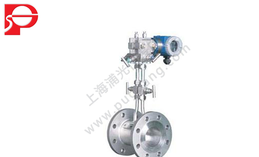
One, the introduction:
LPH series balance flowmeter have greatly improved the traditional throttling device, and the flowmeter has the characteristic such as balance of rectifier, circulation of traditional throttling device is only one aperture, throttling after fluid lost ideal state;And balance meter aperture has multiple functions, can maximize the rectifier into ideal fluid flow field in balance, thus the advantage of the differential pressure flowmeter play incisively and vividly.No moving parts, it is very convenient to install and use simple, saves large straight pipe, greatly reduce the energy consumption required for the fluid to run, is a kind of has a broad application prospect of energy meter.
Second, the measuring principle:
LPH series balance flowmeter is a revolutionary differential pressure type flow instrument, its working principle and other differential pressure flowmeter, are based on the principle of energy conversion in the sealing pipe: in the case of ideal fluid in the pipeline flow is proportional to the square root of the differential pressure.Used to measure the differential value according to the equation to calculate the pipeline flow, the balance disc throttling of flow sensor is a porous rectifier, installed on the cross section of the pipeline, the size and distribution of each hole is based on the special formula and test data, and custom, called the function.When fluid through the function of the disc holes, the fluid will be balanced rectification, eddy current is minimized, form the approximate ideal fluid, through pressure device, can obtain the stability of the differential pressure signal, according to the fluid mechanics in the conservation of mass and the law of conservation of energy can be calculated the volume of fluid flow and mass flow rate, as follows:
Qv = K (delta P/rho) 1/2 or qm = K (delta p. rho) 1/2
Type: qV - volume flow (m3 / h);
Qm - mass flow rate (kg/h);
Delta P - output differential pressure (kpa);
K - flow calibration coefficient;
Rho - fluid density (kg/m3).
Third, scope of application:
LPH series is suitable for almost all fluid balance flowmeter measurement, is a fluid measurement technology is a technology revolution, the current balance of flowmeter has been widely used in chemical, petroleum, metallurgy, electricity, gas, water treatment and other industries.
Four, balance flowmeter features:
High accuracy of measurement:
1, because the balance of flow sensor has the characteristics of the porous structure, able to balance the flow field, reduce the eddy current, vibration and noise signal, the flow field stability is greatly improved, and the table body adopts special precision taking pressure, pipe and special device, make the precision than the traditional throttling devices promoted 5 to 10 times.
3, after real flow calibration, sensor precision of plus or minus 0.3%, plus or minus 0.3%, suitable for trade measurement occasions.
4, geometry size test, sensor precision can be up to + / - 0.5%, plus or minus 1.0%, suitable for process control.
5, balance meter processing repeatability is extremely high, and the traditional throttling device, on the basis of actual flow calibration data, can realize geometry calibration.
Straight pipe low requirements:
1, the flowmeter can flow balance, balance adjustment is stable, and the pressure recovery two times faster than traditional throttling device, greatly reducing the requirement for straight pipe.
2 straight pipe, the majority of cases can be as small as 0.5 D ~ 2 D, especially for special or expensive pipeline, the balancing flowmeter can save a lot of straight pipe.
Permanent pressure loss is low:
Balance meter symmetrical balance design, reduce the formation of vortex flow and turbulent flow friction, reduce the loss of kinetic energy, under the same conditions, compared with the traditional throttling device, the pressure loss is less 70%, close to the venturi tube, thereby saving a considerable cost and worth a lot of promotion.
Wide range than:
1, compared with the traditional throttling devices, greatly improve the measurement range ratio balance flowmeter. The results showed that when the Reynolds number is larger than 50000, select the appropriate aperture parameters, balance flow meter without limit, according to the needs of industrial measuring actual application.
2, regular measurement range ratio of 10:1, choosing the appropriate parameters can do spake or higher.
Good repeatability and long-term stability:
1, balance flow sensor can flow equilibrium stability, repeatability is greatly increased, can achieve + / - 0.1%.
2, circulation of multiple hole dispersion force, no sharp corner wear, its beta remain unchanged for a long time, long term stability is very good;
3, the entire instrument have no moving parts, prolong the service life than traditional the throttle device 5 to 10 times.
Should not be dirt resistant wall:
1, porous symmetrical balance design, reduces the turbulent shear stress and the formation of eddy current, thus greatly reduces the formation of dead area, ensure pore smudgy smooth through multiple media, reduce the chance of a fluid hole blocked.
Wide measuring range:
1, according to the experimental results, we know that balance the performance of the flowmeter, the flow velocity can be from the least to the speed of sound, its smallest Reynolds number can be less than 200, the largest Reynolds number greater than 107;
2, beta optional 0.25 ~ 0.9.
Five, the scope of application:
1, the working temperature, pressure depends on the material and pipe and the flange rating, the highest working temperature can reach 850 ℃, 42 mpa.
2, suitable for LNG cryogenic fluid, liquid air, liquid nitrogen, liquid oxygen, liquid argon, liquid ethylene, liquid hydrogen, liquid chlorine, etc., can effectively prevent the gasification, the measurement effect is best.
3, can measure the gas-liquid two phase, slurry, solid particle measurement, even also can measure the bidirectional flow.
4, left and right sides is symmetrical, so it is very convenient to measure the bidirectional flow.
Six, balance meter technical indicators:
1, pipe diameter range: DN15 ~ DN3000;
2, precision: plus or minus 0.3%, plus or minus 0.5%, plus or minus 1%;
3, straight pipe required: 0.5 D ~ 2 D;
4, pressure loss of the permanent: 1/3 ~ 1/4 orifice plate;
5, range than: 10:1, suitable working condition of data can be done more wide;
6, repeatability: 0.1%;
7, Re: the range of 200-107;
8, beta range: 0.25 ~ 0.9;
9, temperature range, the temperature of the metal pipe to withstand, up to 850 ℃;
10, pressure range: metal pipes can withstand the pressure, up to 42 mpa;
11, dirt resistant: special design and calculation;
12, two-way flow can be measured.
Seven, balance flowmeter installation schematic diagram is as follows:
The installation of the balance valve with three valve group requirements:
The role of balancing valve or valve group
1, adjust the zero point of differential pressure transmitter;
2, prevent the positive and negative differential pressure transmitter, pressure chamber overpressure please click shown below method and pressure pipe connection.
Eight, the pressure transmitter installation requirements:
1, bringing the positive pressure balance flowmeter is pressure pipe into three valve set of positive pressure and differential pressure transmitter, drew balance flowmeter suction side pressure pipe into three valve set of negative pressure chamber to the differential pressure transmitter;
2, differential pressure transmitter in the process piping installation position and the measured medium, in order to obtain good effect of installation, should pay attention to consider the following situations:
A, to prevent the transmitter with corrosive or overheating direct contact with the measured medium;
B, prevent the dross in the pressure tube sedimentation, blocked;
C, the length of the pressure on both sides of the guide pipe should be the same as far as possible;
D, leads the pressure tube pressure on both sides of the fluid column pressure head should keep balance;
E, pressure pipe installation in the temperature gradient and temperature fluctuation in the least.
3, measuring the liquid flow rate, differential pressure transmitter shall be installed beside the pipeline under test or below, so that air bubbles into the pipeline.
4, measuring gas flow rate, differential pressure transmitter shall be installed beside the pipeline under test or above, in order to accumulate the liquid to flow into the pipeline.
5, measurement of steam flow, differential pressure transmitter shall be installed at the bottom of the pipe to be tested, so that condensate can fill in the pressure in the tube.Should pay special attention to the measurement of steam or other high temperature medium, to prevent contact with differential pressure transmitter temperature transmitter using limit temperature of the medium.
Nine, temperature, pressure transmitter installation requirements:
1, measuring, superheated steam medium must be integrated temperature transmitter and pressure transmitter, dynamic compensation.Measurement of saturated steam medium, must want to add pressure transmitter, dynamic compensation.
2, measuring, natural gas, coal gas medium must plus a dynamic compensation of pressure transmitter, and use of safety barrier and explosion-proof device of the transmitter.3, measurement of hot water medium, heat is need to show, must add integrated temperature transmitter, otherwise the integrated temperature transmitter.
4, integrated temperature transmitter is installed on the pipeline under test, have to balance the flow meter paragraph 5 d just before or after or outside temperature probe tip should be inserted into the straight section of 2 d exceed half pipe diameter, to ensure the accuracy of measurement.
5 pressure, differential pressure transmitter, pressure points, must before the balance meter view of straight pipe section 5 d or 2 d after straight pipe, meantime switch valve.For the installation of integrated temperature transmitter and pressure transmitter, in principle should accord with conventional installation specification can meet the requirements of the system, its specific installation requirements can see separate installation instructions.
Ten, balance the flowmeter sensors connected to the process piping installation method:
1, and piping connection points of the following four: (1) the flange connection;(2) direct welding;(3) the wafer;(4) pipe.
2, pressure on the pipeline installation direction points measuring gas, steam, liquids, such as three ways, as follows
(1) to measure gas flow pressure direction
(2) to measure steam flow pressure direction
(3) the direction of liquid flow pressure measurement
(4) the installation steps
A, select the installation of a straight line is good, sensor and process piping connections can be flange, the clamp, straight welded tube, square, specific connection according to order products.
B, best before installing, the upstream pipe blowing clean and prevent pipe welding slag into the instrument such as rust;
C, split type guide pipe size can choose ¢14 x4. 5-18 x4 ¢. 5 of the seamless steel tube (thick wall tube should be used when high pressure).
Eleven, debugging and running of the balance meter:
, based on the principles of installation and application after the installation is complete, before the system debugging to check all equipment, fittings, valves, pipes, wires, terminal blocks, such as signal plug whether complete, correct and reliable, pipes and equipment have blocked, leak phenomenon, connect the wire and the signal point wrong, short circuit, break line, the problem such as poor contact, confirmed by the check and correct the rear can be carried out system debugging, and debugging steps are as follows:
1, the pressure tube drainage:
A, will balance the flow meters on both sides of the valve open (note: must speak valve is opened entirely);
B, the three on either side of the valve group is negative pressure valve closed, in the middle of the balancing valve open;
C, will bring pressure tube are sent without negative pressure valve opens, on both sides for drainage.Clean pressure tube.
2, pressure pipe condensing:
A, close the drain valve, let the media in the lead in the pressure tube natural condensation, until the whole pipe full of condensed water (about 4 hours).
B, when the led has enough of condensed water pressure tube, the three valve group is negative pressure on both sides of the valve can be opened (at this point in the middle of the balancing valve is still in an open position), and let the condensed water into the differential pressure transmitter is negative pressure chamber, respectively.Due to the condensed water deposition will take time, so start the indications of the differential pressure transmitter will not accurate, such as condensed water completely filled the whole measurement system (including pressure, pressure pipe and differential pressure transmitter is negative pressure chamber), differential pressure transmitter indication of opportunities tend to be normal (takes about 2 hours).
C, differential pressure transmitter exhaust:
In order to ensure the residual air out of the differential pressure transmitter is negative pressure cavity clean, the transmitter is negative pressure chamber on the exhaust gas.
4, zero differential pressure transmitter:
A, closed differential pressure transmitter is negative pressure valve on the room.
B, the three on either side of the valve group is negative pressure valve closing (at this point in the middle of the balancing valve is still in an open position).
Note: differential pressure transmitter zero points for attention:
A, zero adjustment screws and range adjustment screws do not confuse, make a mistake.Installation site do not
For differential pressure transmitter range adjustment;
B, transducer zero pressure chamber and on both sides of the pressure tube temperature must be the same, if the two sides
Have a temperature adjustment of zero will produce drift over time;
C, if in the field with a transmitter to carry on the positive and negative transfer compensation, should be smuggled in the state of zero adjustment.If large amount of migration, the migration compensation to differential pressure transmitter.
Twelve, pipeline size and shape reference weight is as follows:
Pipe diameter DN(mm) | The length of the L(mm) | With internal thread (RC) | Refer to the weight ( Kg) |
| 10 | 228 | A quarter | |
| 20 | 228 | A quarter | |
| 25 | 228 | A quarter | |
| 32 | 228 | A quarter | |
| 40 | 228 | A quarter | |
| 50 | 228 | A quarter | |
| 65 | 292 | 1/2 | |
| 80 | 292 | 1/2 | |
| 100 | 292 | 1/2 | |
| 125 | 312 | 1/2 | |
| 150 | 312 | 1/2 | |
| 200 | 312 | 1/2 | |
| 250 | 355 | 1/2 | |
| 300 | 395 | 1/2 | |
| 350 | 395 | 1/2 | |
| 400 | 430 | 1/2 | |
| 450 | 460 | 1/2 | |
| 500 | 500 | 1/2 | |
| 600 | 560 | 1/2 |
13, wafer size and shape reference weight as follows:
Pipe diameter DN(mm) | The length of the L(mm) | With internal thread (RC) | Refer to the weight ( Kg) |
| 10 | 102 | A quarter | 10 or less |
| 20 | A quarter | ||
| 25 | A quarter | ||
| 32 | A quarter | ||
| 40 | A quarter | ||
| 50 | A quarter | ||
| 65 | A quarter | ||
| 80 | 1/2 | 15 | |
| 100 | 122 | 1/2 | 16 |
| 125 | 1/2 | ||
| 150 | 1/2 | 29 | |
| 200 | 1/2 | 33 | |
| 250 | 1/2 | 45 | |
| 300 | 1/2 | 57 | |
| 350 | 1/2 | 69 | |
| 400 | 1/2 | 87 | |
| 450 | 1/2 | 96 | |
| 500 | 1/2 | 111 | |
| 600 | 1/2 | 159 | |
| 700 | 218 | 1/2 | 200 |
| 800 | 228 | 1/2 | 220 |
| 900 | 238 | 1/2 | 260 |
| 1000 | 258 | 1/2 | 340 |
| 1200 | 248 | 1/2 | 380 |
| 1400 | 258 | 1/2 | 520 |
| 1600 | 278 | 1/2 | 740 |
| 1800 | 298 | 1/2 | 910 |
| 2000 | 318 | 1/2 | 1130 |
14, straight weld shape size and reference weight is as follows:
Pipe diameter DN(mm) | The length of the L(mm) | With internal thread (RC) | Refer to the weight ( Kg) |
| 10 | 102 | A quarter | 10 or less |
| 20 | A quarter | ||
| 25 | A quarter | ||
| 32 | A quarter | ||
| 40 | A quarter | ||
| 50 | A quarter | ||
| 65 | A quarter | ||
| 80 | 1/2 | 15 | |
| 100 | 122 | 1/2 | 16 |
| 125 | 1/2 | 21 | |
| 150 | 1/2 | 29 | |
| 200 | 1/2 | 33 | |
| 250 | 1/2 | 45 | |
| 300 | 1/2 | 57 | |
| 350 | 1/2 | 69 | |
| 400 | 1/2 | 87 | |
| 450 | 1/2 | 96 | |
| 500 | 1/2 | 111 | |
| 600 | 1/2 | 159 |
15, balance flowmeter selection table:
| Specifications and code | Code meaning | |
| LPH | (balance meter) | |
| size | -XXX | XXX said diameter: such as 100 DN100 said |
| The table body material | -C F M U | C - carbon steel F-304 M-316L U - carbon steel pipe lining F46 |
| The disc material | F M U | F-304 M-316L U- F4 |
| Temperature range | - 1 2 | 1 - medium under normal temperature, the temperature < 80 ℃ 2 - high temperature medium, temperature < 600 ℃ |
| Pressure range | 1 2 3 4 5 | 1 - work pressure 0.6 MPa or less 2 - work pressure 1.0 MPa or less 3 - work pressure 1.6 MPa or less 4 - work pressure 4.0 MPa or less 5 - special pressure |
| Equipped with accessories | - 1 2 3 4 5 6 A B | 1 - matching flange installation (including bolts, nuts, washers) 2 - matched condenser 3 - matching isolator 4 - matching three valve group (or a valve) 5 - matching differential pressure transmitter 6 - matching flow integrating instrument A - one-piece B - two-piece |
| The product type | - 1 2 3 4 5 | 1 - the flange to take pressure 2 - the wafer 3 - straight welded type 4 - the integration of intelligent temperature (with pressure compensation) 5 - square tube |
16, design selection and order notes:
1, pipe size: diameter x wall thickness (mm);
2, measuring medium name: medium density (kg/m3);
3, set the maximum flow: meter on the range of limit (kg/h or m3 / h);
4, process of minimum flow: (kg/h or m3 / h);
5, work pressure (Mpa);
6, work temperature: (° C);
7, such as with our company, please provide together: intelligent flow totalizer.especially pressure range, or pressure transmitter type, range;Temperature range, or models, range temperature transmitter.

